Home › Unlabelled ›
Time Delay Relay Symbol : Time Delay Electromechanical Relays Worksheet Digital Circuits : Either can be supplied as fixed or resistor adjustable types.
Time Delay Relay Symbol : Time Delay Electromechanical Relays Worksheet Digital Circuits : Either can be supplied as fixed or resistor adjustable types.. It also has a potentiometer to adjust the time delay, where here we have used 9 v battery and 5v optional relay for switching the ac load. Timing gadgets are utilized to cut on or off pilot gadgets at a preset time. I just started getting into arduino. Other types of tdrs simply use the same contact symbols as those for relays. Time delay relays are simply control relays with a time delay built in.
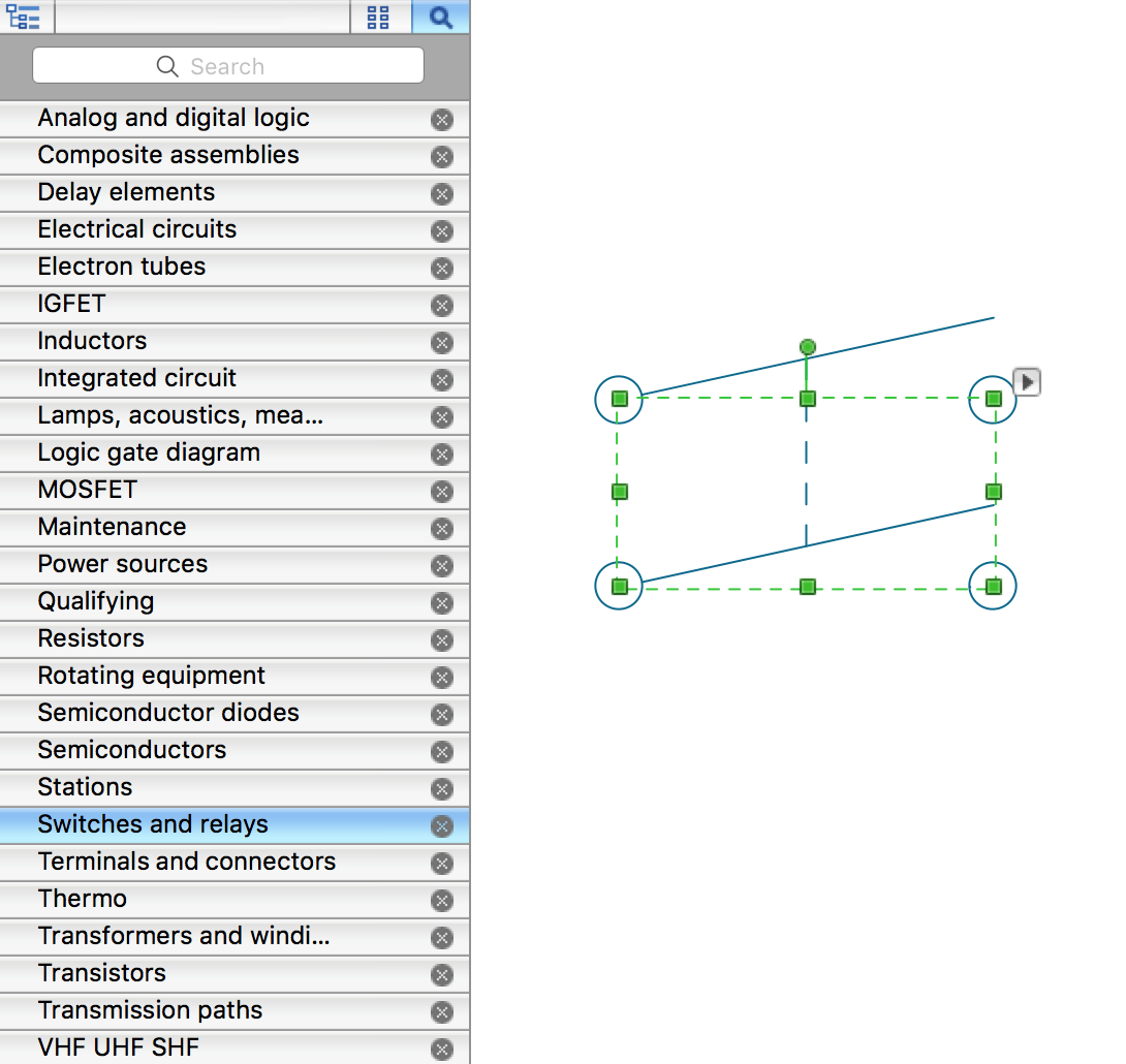
The picture below is switches and relays symbols including switch 1p, isolator 1p, circuit breaker 1p, spring return, time delay break, fuse, relay contacts, relay. When the time has expired, the contacts close — and remain in fact, they are the only tdrs for which special contact symbols have been assigned. With 8 time ranges selected shortest 0.1s most up to 1 hour protection against power reversal protection diode, better protection module can be accessed by a large current load (250v ac 10a or 30v dc 10a) with delay adjustment potentiometer clockwise adjustment time longer. The reason for using delaystart += delay_time; Measuring relay the asterik is replaced by letters or symbols related to the relay.
Electrical Symbols Switches And Relays from www.conceptdraw.com It also has a potentiometer to adjust the time delay, where here we have used 9 v battery and 5v optional relay for switching the ac load. I just started getting into arduino. Both military and commercial versions are offered. Either can be supplied as fixed or resistor adjustable types. Time delay relays are simply control relays with a time delay built in. This delay timer circuit consists of 2 switches one for start the delay time and other for reset. I am looking to build a circuit that would control an output relay. Timer switch symbol wiring schematic diagram.
Inverse time delay is achieved in induction disc relay by providing a permanent magnet in such a way, that, when disc rotates, it cuts the flux of permanent magnet.
Dayton time delay relay wiring diagram download. It also has a potentiometer to adjust the time delay, where here we have used 9 v battery and 5v optional relay for switching the ac load. Timing devices are used to cut on or off pilot devices at a preset. When the time has expired, the contacts close — and remain in fact, they are the only tdrs for which special contact symbols have been assigned. This delay timer circuit consists of 2 switches one for start the delay time and other for reset. Discuss with your students how the contact symbols make sense (arrows on. The reason for using delaystart += delay_time; Plc mechanical timing relays plc (programmable logic controllers) these pictures of this page are about:time delay relay symbol. Their purpose is to control an event based on time. The time delay relay circuit described here is intended for this purpose. Some or all industrial control systems need timing operations. Time delay relays are simply control relays with a time delay built in. Due to this, current is induced in the disc which slows down the movement of the disc.
Most of the time, a small voltage or current is used to switch other voltages or overcurrent relay with delayed action. Inverse time delay is achieved in induction disc relay by providing a permanent magnet in such a way, that, when disc rotates, it cuts the flux of permanent magnet. Though there are many types of timers and time delay relay. Timing gadgets are utilized to cut on or off pilot gadgets at a preset time. On a control relay, it happens when voltage is applied and removed from the.
Electrical Symbols For Relays Wiring Diagrams Comfortmaker Air Handler Wiring Diagram Jaguars Karo Wong Liyo Jeanjaures37 Fr from static-resources.imageservice.cloud Timing gadgets are utilized to cut on or off pilot gadgets at a preset time. With 8 time ranges selected shortest 0.1s most up to 1 hour protection against power reversal protection diode, better protection module can be accessed by a large current load (250v ac 10a or 30v dc 10a) with delay adjustment potentiometer clockwise adjustment time longer. It gives power to the device only after one to two minutes of delay after relay remains latched as long as the voltage level in the mains is normal. A few or all mechanical control frameworks need timing activities. On a control relay, it happens when voltage is applied and removed from the. Auxiliary relay with mechanical contacts auxiliary relay, block symbol. Their purpose is to control an event based on time. I will need an adjustable time delay (possibly displayed time) after the switch is released, then the output would go on for an adjustable time (also possibly displayed) before shutting off.
Either can be supplied as fixed or resistor adjustable types.
Both military and commercial versions are offered. I am looking to build a circuit that would control an output relay. Symbols are short at icon menu. Auxiliary relay with mechanical contacts auxiliary relay, block symbol. Though there are many types of timers and time delay relay. Capacitor c2 keeps the base bias of t1 steady so that relay clicking can be avoided. Dayton time delay relay wiring diagram download. I will need an adjustable time delay (possibly displayed time) after the switch is released, then the output would go on for an adjustable time (also possibly displayed) before shutting off. Most of the time, a small voltage or current is used to switch other voltages or overcurrent relay with delayed action. Due to this, current is induced in the disc which slows down the movement of the disc. Some or all industrial control systems need timing operations. Discuss with your students how the contact symbols make sense (arrows on. Timer switch symbol wiring schematic diagram.
Symbols are short at icon menu. Inverse time delay is achieved in induction disc relay by providing a permanent magnet in such a way, that, when disc rotates, it cuts the flux of permanent magnet. I am looking to build a circuit that would control an output relay. Timing devices are used to cut on or off pilot devices at a preset. Plc mechanical timing relays plc (programmable logic controllers) these pictures of this page are about:time delay relay symbol.
Time Delay Electromechanical Relays Worksheet from www.learningelectronics.net Timing devices are used to cut on or off pilot devices at a preset. Td2 series time delay relays are available for delay on operate or delay on release operation. Most of the time, a small voltage or current is used to switch other voltages or overcurrent relay with delayed action. It also has a potentiometer to adjust the time delay, where here we have used 9 v battery and 5v optional relay for switching the ac load. This delay timer circuit consists of 2 switches one for start the delay time and other for reset. The relay are switching electrical devices activated by signals. Both military and commercial versions are offered. With 8 time ranges selected shortest 0.1s most up to 1 hour protection against power reversal protection diode, better protection module can be accessed by a large current load (250v ac 10a or 30v dc 10a) with delay adjustment potentiometer clockwise adjustment time longer.
I am looking to build a circuit that would control an output relay.
Due to this, current is induced in the disc which slows down the movement of the disc. Both military and commercial versions are offered. Plc mechanical timing relays plc (programmable logic controllers) these pictures of this page are about:time delay relay symbol. Symbols are short at icon menu. Either can be supplied as fixed or resistor adjustable types. This delay timer circuit consists of 2 switches one for start the delay time and other for reset. When the time has expired, the contacts close — and remain in fact, they are the only tdrs for which special contact symbols have been assigned. It gives power to the device only after one to two minutes of delay after relay remains latched as long as the voltage level in the mains is normal. Timing devices are used to cut on or off pilot devices at a preset. With 8 time ranges selected shortest 0.1s most up to 1 hour protection against power reversal protection diode, better protection module can be accessed by a large current load (250v ac 10a or 30v dc 10a) with delay adjustment potentiometer clockwise adjustment time longer. The picture below is switches and relays symbols including switch 1p, isolator 1p, circuit breaker 1p, spring return, time delay break, fuse, relay contacts, relay. On a control relay, it happens when voltage is applied and removed from the. I am looking to build a circuit that would control an output relay.